AnalogEVSE
A basic analog SAE J1772 charge
controller
Last updated: 2023-08-31
|
|
1.
Overview
AnalogEVSE is a simple
SAE J1772 compliant charge controller for EVs. The charge current
can be adjusted from 8A to 64A with a resistor or control voltage.
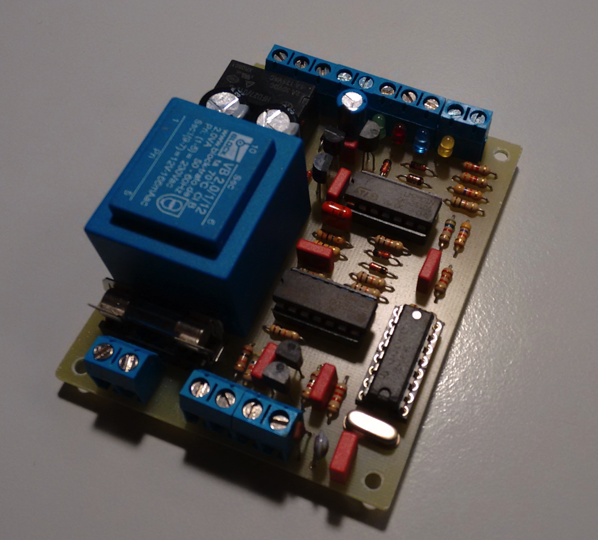
The circuit resides on a single PCB (6.5 cm x 8.4 cm) containing
both the power supply and the pilot signal management. The PCB is
designed to fit into a 4 unit DIN rail enclosure. This makes the
new PCB 30% smaller than the previous version. Additionally, the
frequency calibration is no longer equired. The circuit generates
the pilot signal, measures its voltage levels and operates a relay
which can be used for switching on the high current relay.
The circuit was designed using only common and inexpensive parts.
The main components are 2 LM2901 or LM239 quad comparators (LM339s
with extended temperature range), a CD 4060B, a few transistors
and a handful of passive parts. Everything is analog and there is
no software. Virtually any transistor of the right type (NPN/PNP)
will work. The cost for all components should not exceed 50€. The
PCB is single sided with large tracks and can easily be reproduced
by hobbyists.
The PCB has the following connectors:
- 230V mains
- Relay output
(isolated) 250V/500mA max. 1x make contact (NOC), 1x toggle
- Pilot signal
- Resistor for duty
cycle/charge current selection
- LEDs
- Idle
(white/yellow)
- EV connected
(green)
- Charging (blue)
- Error (red)
Most other analog EVSEs I
know generate the positive part of the pilot signal only. The car
doesn't use the negative signal so charging works with many cars
even if this does not comply with the J1772 standard. However, the
negative half-wave is used for the diode check which is an
essential safety feature. AnalogEVSE has a J1772 compliant
-12V/+12V pilot signal and supports the diode check. Rain water,
dirt or a child's fingers will not be able to turn on the EVSE.
With no EV connected, the Pilot signal is at 12V DC.
If the EV requests ventilation the circuit will close the relay
and enable charging. Since there is no extra relay for a
ventilator the circuit must be used outside only with lead acid
batteries.
The EV will start charging as soon as the connector is plugged in.
There is no extra button for triggering the operation.
The following EVs are known to work with AnalogEVSE:
- Renault ZOE (all
models)
- Hyundai IONIQ
electro
- Mercedes B-Class ED
- BMW i3
- BMW i8
- BMW eDrive
- Tesla Model S, 3 and
X
- Smart ED (old and
new model)
- Toyota Prius Plugin
- Kia Soul EV
- VW Passat GTE
- VW Golf GTE
- VW E-Up!
- VW E-Golf
- Nissan Leaf
- Audi A3 e-tron
- Opel Ampera-e
2. Why Another EVSE?
There are three major
reasons: curiosity, price and simplicity. Commercially available
charge controllers (Phoenix Contact, Wago..) are expensive and
provide a set of features that I don't need. I rarely switch
between charge currents and if I do I want to do it easily
(preferably with a rotary switch). I also want some sort of status
display but it doesn't have to be a text display. I'll never use a
RTC, network, wifi or sophisticated authentication.
So I studied the SAE
J1772 standard and its simplicity is striking. Making a
basic EVSE with analog circuitry is pretty straightforward. I have
found a few analog EVSE circuits on the internet but they are
either too minimalistic/unsafe (BareEVSE),
ignore parts of the standard (only +12V pilot signal) or come without
schematics. So I decided to design a simple analog circuit
that complies with J1772, delivers a +/-12V pilot signal and
supports the diode check for safety reasons.
The main focus of my design is simplicity. The new design uses
less components, has a smaller PCB, lower power consumption and
eliminates the need for frequency calibration by using a quartz
oscillator. The layout is simple and the circuit is tolerant
against assembly mistakes. Debugging is relatively simple and can
be done using basic equipment which makes this design suitable for
use in less developed countries.
3. Circuit States & LEDs
The following table shows
the possible states of the circuit and the corresponding LEDs.
|
LED yellow
Idle
|
LED green
Connected |
LED blue
Charging |
LED red
Error |
No
EV
|
on
|
off |
off |
off |
EV
connected
|
off
|
on
|
off |
off |
EV
charging
|
off |
off |
on
|
off |
EV
requests ventilation
|
off |
off |
on |
off |
Pilot
signal short circuit
|
off |
off |
aus |
on2 |
Diode
test failure
|
off |
off |
aus |
on1,2 |
1 with EV
connected
2
J1772 requires -12V DC. See chapter Limitations.
Note: Using an
RGB LED with a common anode is possible since all LEDs have one
common pin. Use of the Idle LED is optional. However, the other
three LEDs (red, green, blue) must either all be connected or
none at all. Otherwise, they will display wrong status colors.
4. Charge Current
Selection
The charge current can be
set with an external resistor according to the following table.
Intermediate values are supported since the circuit is all analog.
Using a potentiometer is also possible. Please note:
- the
resistance/current ratio is not linear
- the currents listed
below are approximate values which were calculated from
oscilloscope measurements. Due to component tolerances or
temperature drift, the charge current may differ in a real
application.
Rext
|
Charge
current
|
--
|
8A
|
220k
|
10A
|
100k
|
12A
|
56k
|
16A
|
33k
|
20A
|
22k
|
24A
|
15k
|
27A
|
|
Rext
|
Charge
current |
| 10k |
32A |
| 6k8 |
36A |
| 4k7 |
40A |
| 3k3 |
45A |
| 2k7 |
48A |
2k2
|
50A
|
1k5
|
64A
|
|
Alternatively, the charge current can be selected with a control
voltage between 1,5V (64A) and 10V (8A), e.g. by a solar array
controller.
5. Circuit Description
Power supply
The
power supply is a simple +/-12V stabilized circuit using
78L12/79L12. The current requirements are so low that a simple
half-wave rectifier is sufficient.
Note:
the negative supply voltage requires a few mA load in order to
remain stable. Therefore, the onboard power LED is mandatory.
Square wave signal
The
1kHz square wave signal is generated by a quartz oscillator and
filtered into a triangle-ish signal by an RC element. A voltage
comparator is used for transforming it into the square wave. The
comparator's reference voltage defines the duty cycle and can be
adjusted with the external resistor. Using no external resistor
sets the default charge current (8A).
Voltage window
detection
The
square wave signal is split into its negative and positive
half-waves. Both are rectified and filtered to a stable DC
(peak) voltage. The negative part must remain below -8V at all
times (diode check) or the circuit will go to error state.
If the
positive part is below 10V the EV connected LED will light up.
If it is between 7V and 2V the relay will switch on and the
charging LED will light up. For all positive voltages below 2V
(short circuit) the circuit will go to error state. The various
reference voltages are generated by a string of resistors
forming a multi-voltage divider.
Pilot signal
The
pilot signal is generated by two comparators and boosted by a
complementary transistor stage. It is at +12V DC when no EV is
connected.
Relay driver
The relay driver has a
47μF capacitor for debouncing the relay. A bouncing relay can
destroy the EV's charger when using 3-phase charging (e.g.
Renault ZOE).
LED drivers
The LED driver uses
Zener diodes with varying forward voltages so that only one LED
lights up at a time.
6. Emergency Shutdown
An emergency shutdown
is not part of the circuit. However, it can be implemented
easily with a switch that interrupts the 230V power supply. This
will remove power from the circuit and the relay will open.
Please note that an emergency shutdown should only be used in
cases of emergency because the EV prefers to shut down the
charging process gracefully.
Note: the
emergency shutdown circuit my be subject to legal requirements.
7. Access Control
There are several ways
for implementing a simple mechanical access control:
- a lockable emergency
shutdown button that can only be enabled with a key
- a 230V capable key
switch in series with the emergency shutdown button
- a low-voltage key
switch in the pilot signal wire. If the switch is off the
circuit will not sense the EV and the controller will remain
inactive.
8.
Limitations
- The circuit is
designed for charge currents up to around 64A. I have not
investigated higher currents than 32A since my home
installation is limited to 32A.
- EVs requesting
ventilation (lead acid batteries) will be able to charge with
AnalogEVSE but the charging station must be located in a well
ventilated area (preferably outside) as the controller cannot
switch on ventilation. However, this seems to be an academic
issue with modern EVs.
- The pilot signal
carries a square wave in error state (standard says it should
be -12V). However, the relay remains open. Even though this
does not comply with the standard I cannot think of any threat
it would pose. Even if for some reason the car thinks it
should be charging it will be without voltage.
- AnalogEVSE has been
tested with a wide variety of EVs. However, I cannot give any
guarantees that it will work with your EV. That being said, I
see no reason why it shouldn't work with other EVs. I have
been charging my ZOE for more than 3 years using AnalogEVSE
controllers exclusively.
- LM339 are specified
for the temperature range 0 - 70°C. For outdoor applications
it is advisable to use LM2901 or LM239 which have an extended
temperature range of -25 - 85°C. These are included in the
kits.
9. Hints & Modding
9.1 Load Balancing
If two EVs must be charged
from a single mains supply the generic solution would be to assign
half of the supply power to each EV. This will ensure that the
maximum power of the supply line will never be exceeded even if
both EVs are charging simultaneously. However, this solution will
"waste" half of the supply power if only one EV is connected. This
EV could be charged at twice the power and finish charging much
quicker.
In this scenario, load balancing will dynamically adjust the
available charging power, depending on the number of charging EVs.
A charging station with 2 AnalogEVSE controllers can be
implemented with just two resistors, using the unused second relay
contact. The two resistors (R1 and R2) are connected in parallel
as long as only one EV is charging. If two EVs are charging one of
the resistors (R2) will be disconnected. This raises the
resistance and halves the current.
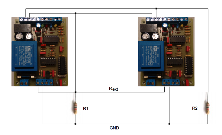
The values of R1 and R2 are dependent on each other and must be
chosen carefully in order not to overload the mains supply under
all circumstances. First we must select the full throttle current
for a single charging car. We can then look up the corresponding
current selection resistor Rext1
from the table.
Then we determine the resistor Rext2 for half the
current in the same manner. Now we can calculate the two
resistors:
R1 = Rext2 / 2
R2 = 1 / (2 / Rext1 - 1 / R1)
An example:
One EV will charge with 32A, two EVs will charge with 16A each.
Using the table we find:
Rext1 = 10k (for 32A)
Rext2 = 56k (for 16A)
Now we can apply the formula above for calculating R1 and R2. If
there are no matching standard resistors we can either use a
trimpot or a combination of multiple resistors.
R1 = Rext2 / 2 = 56000 / 2 = 28000 closest
standard value 27k
R2 = 1 / (2 / Rext1 - 1 / R1) = 1 / (2 / 10000 -
1 / 27000) = 6136
closest standard value
6.8k
If the calculated value is not readily available it is usually
better to choose a higher value so that the current does not
exceed the limit.
9.3 Additional Hints
- If you intend to set
the controller to a fixed charging current the terminal P2 and
R2 can be replaced with the pot RV2 which can be set to the
desired current. The pot's value can be calculated from using
R2 (10k) and the value of Rext in parallel,
according to the table.
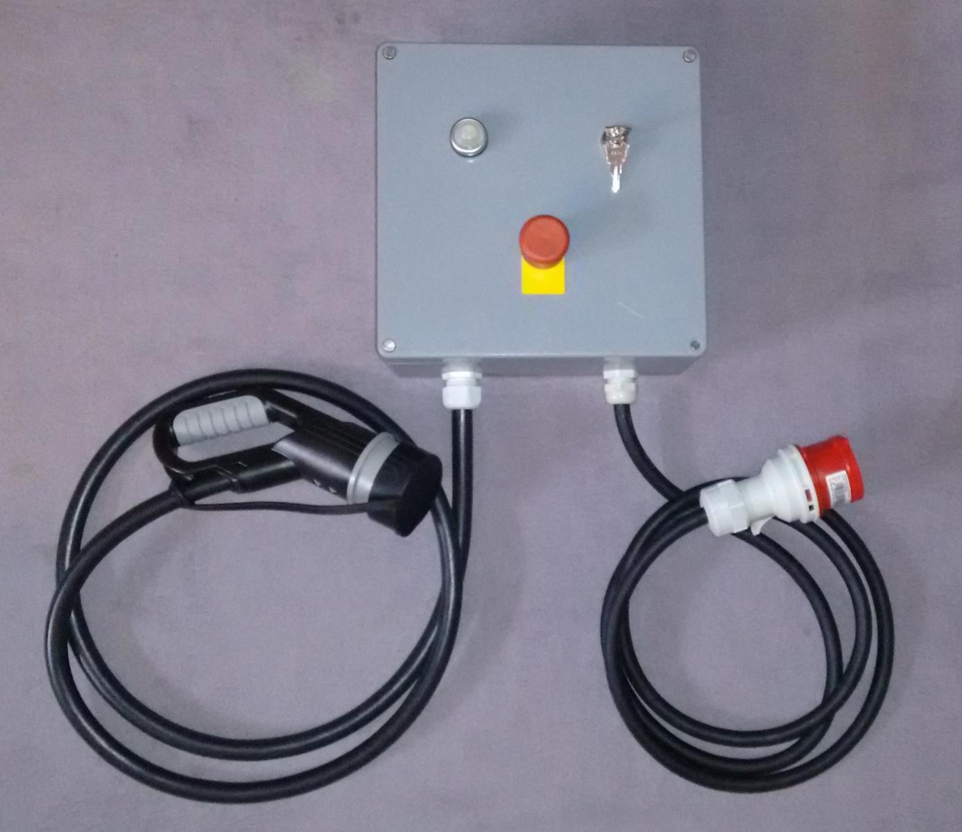
- Make sure you use a
suitable enclosure (IP64 or better) and seal it properly when
mounting the EVSE outdoors. Water and electricity do not go
together well.
- When wiring the box
make sure you use wire colors that comply with national or
company regulations.
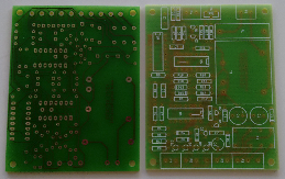
10. Construction Manual
10.1 General Hints
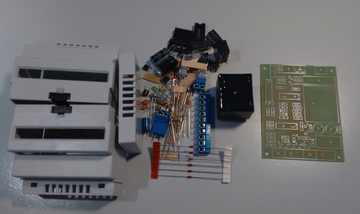
The kit contains all
components that are required for assembling and testing the
AnalogEVSE controller. Populating the PCB requires a certain
amount of soldering experience. Misplaced or misoriented
components will lead to erroneous behavior and may be dangerous.
Please read this manual before starting the assembly.
10.2 Safety
This circuit has 230V
mains voltage and low voltage on a single PCB. When working with
the controller, please be extra careful if the PCB is connected to
the mains.
10.3 Tools
You will need the
following tools:
- a small soldering
iron and thin solder wire
- a wire cutter
- small pliers for
bending wires
- a multimeter
10.4 Preparations
Identify all components
using the BOM and make sure the kit is complete.
Hints for the kit:
- the zener diodes
have pieces of tape
- sometimes LM2901 ICs
are unavailable so I have to substitute them with LM239 or
LM339
10.5 Assembly
10.5.1 General Hints
The basic assembly
procedure goes as follows:
- power supply
assembly and test
- controller assembly
and test
- DIN rail enclosure
installation
All components should be
soldered into place that they touch the surface of the PCB free of
clearance. Transistors and the voltage regulators should be
installed so that their pins are approximately 7mm long.
10.5.2 Assembly and
Test of the Power Supply
Components: P1, P4, P6, F1, T1, D1, D2,
C1, C2, C4, C5, U1, U2
The PCB has pads for different types of transformers. First,
solder the transformer into the matching holes. Check the polarity
of diodes and electrolytic capacitors. The voltage regulators U1
and U2 are different types and must be mounted in the correct
location. It is advisable to slide P4 and P6 together before
mounting them onto the PCB.
When all components have been mounted properly insert the fuse and
connect to 230V~ mains voltage. You
should be able to measure +12V between 0V (P4 Gnd) and pin 3 of
the IC sockets of U3/U5 and
-12V between 0V (P4 Gnd) and pin 12 of these IC sockets. If this is not the case power down
immediately and look for the error.
- Did you bridge
traces with excess solder?
- Did you insert the
fuse and is it still intact?
- Can you measure a
low AC voltage at the transformer's secondary?
- Are the diodes and
electrolytic caps oriented properly?
- Can you measure a DC
voltage at the pins of the electrolytic
caps?
- Are the voltage
regulators oriented properly?
- Did you swap the
voltage regulators?
10.5.3 Assembly and
Startup
Note for owners of
PCB v2.0.4 (Oct. 2021 and later): resistor R20 is not used
and must be bridged with a wire
Mount the diodes D10 and D12 first and use the clipped off wire
ends for the two wire bridges, then mount the IC sockets. Please
make sure you don't forget these wir bridges as it will be nearly
impossible to retrofit them later. Install the remaining terminals
so that their guiding rails interlock. You can also slide them
together before mounting them onto the PCB. You can now install
and solder all remaining components starting with the smallest
pieces. When all components are
assembled insert U3, U4 and U5 into their sockets. You may need
to bend the pins slightly inwards.
Check the PCB carefully and connect it to the main voltage.
Only the yellow idle LED should light up. If this is not the case
switch off immediately and look for the error.
- Did you bridge traces
with excess solder?
- Can you measure the
supply voltage?
- Did you place and
orient the diodes correctly?
- Did you place the
transistors correctly?
- Did you orient the
ICs correctly?
10.5.4 DIN Rail Enclosure
Installation
The recommended (or the
one that comes with the kit) DIN rail enclosure has a little
plastic stabilizer in the center of the front and back access
ports. Unfortunately, this tiny piece of plastic blocks access to
the terminals for LEDs and the pilot signal. However, it can
easily be removed using a sharp knife/wire cutter and a small
file. If done carefully, the procedure will not be visible.
10.5.5 BOM
Download the BOM.
11.
Testing
Once the PCB is
completed the interesting question arises: will it work? In
order to test the functionality of the assembly you need an EV
simulator and an oscilloscope for troubleshooting.
The EV simulator is a
simple circuit which mimics the correct behavior of the EV and
can simulate two distinct errors. The simulator is available as
a kit from OpenEVSE but it is so simple that it can be
built point to point.
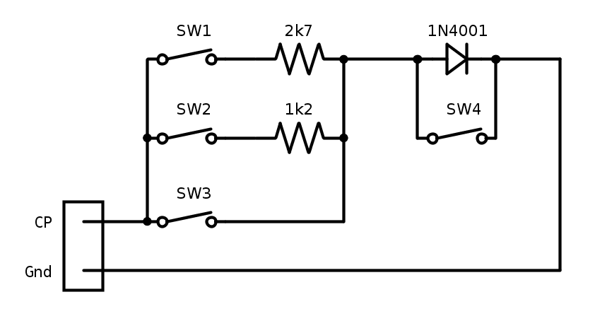 |
SW1
|
EV connected
|
SW2
|
EV charging (with SW1 closed)
|
SW3
|
CP short circuit
|
SW4
|
Diode failure
|
When the pilot
signal of the AnalogEVSE PCB is connected to the EV simulator
you can test the following conditions using the on-board LEDs:
SW1
|
SW2
|
SW3
|
SW4
|
State
|
LED
Idle
|
LED
Connected
|
LED
Charge
u. Relais
|
LED
Error
|
off
|
off |
off |
off |
Idle
/ No EV
|
on
|
off |
off |
off |
on
|
off |
off |
off |
EV
connected |
off |
on
|
off |
off |
on
|
on
|
off |
off |
Charging |
off |
off |
on
|
off |
| don't care |
on
|
off |
Pilot
signal short circuit |
off |
off |
off |
on
|
| SW1 and/or SW2 on |
on
|
Diode
error |
off |
off |
off |
on
|
12. Downloads
AnalogEVSE was designed using KiCAD 5.0.1
and has been migrated to KiCAD 7.0.6. KiCAD is a free
EDA software package available for Windows, Linux and Mac OS X.
The KiCAD
project files used to be hosted on Github. However, I
strongly disagree with the latest changes requiring 2FA, so I
abandoned github. The git repository can be downloaded below
instead. Please remember that the latest revisions may not work.
|
| KiCAD Project: |
analogevse-kicad-v2.0.5.zip
Files of the KiCAD project
|
|
Schematics:
|
For
a quick look: Analogevse-v2.0.5-schematic.pdf
Please use the KiCAD files for reference or development as
these will be updated constantly.
|
|
Zip-Archive of Version 1.8:
|
This archive contains the full website as
it was during version 1.8
analogevse-v1.8.zip
If your circuit doesn't seem to match the description on
this page then these files are probably what you need.
|
|
KiCAD:
|
Downloads
KiCAD
Software Download
|
|
Wiring Diagram:
|
Wiring-AnalogEVSE-2.0.X.pdf
Wiring
Diagram for a wallbox using the AnalogEVSE
controller and details about load balancing.
|
|
13. Ordering
You can order the PCB or a full kit from
me using the email address listed below. Postage is included for
shipping within Germany. Please check the table below for
approximate postage and contact me for the exact amount when
placing your order. Note that postage is only required once per
order (not per item).
Delivery time for a kit is approximately
one week since I may have to obtain some components before
shipping. PCBs can be shipped immediately as long as my stash
lasts.
Please note: if you order the PCB
only you will need to find a number of components that match the
footprint on the PCB (e.g. the transformer). Moreover, the PCB
size is tuned exactly to the DIN rail enclosure I use. The kit
includes all components that will match the PCB and the PCB will
fit nicely into the box.
|
|
Price
|
Germany |
EU
|
Worldwide
|
PCB
Professionally manufactured single sided PCB
with solder resist and assembly pressure
|
|
10€
|
no
postage |
+ 4€
postage
|
+ 8€
postage |
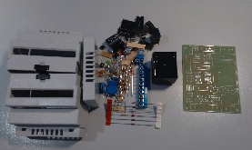
Kit
All components required for a complete controller:
PCB, electrical components, transformer, DIN rail enclosure
Without
external resistor Rext
|
|
50€
|
no
postage |
+ 4€
postage |
+ 12€
postage |
12.
Disclaimer
(C) 2015 - 2023
Bernhard Walter
AnalogEVSE is open
source hardware. I designed it for my needs and although I
designed it carefully I cannot guarantee that it is free of
errors. Use it at your own risk.
You are free to build, copy and modify the circuit and its
documentation as long as you include the original copyright
notice and this disclaimer.
Use caution when
working with high voltage. It may kill you.
I am not responsible for the content of linked external web
pages.
Contact: analogevse@web.de
Changelog:
2015-11-19: correction of minor error in PCB layout. Version
changed from 1.3 to 1.4.
2015-11-22: PCB redesign for a standard transformer
2016-09-10: version 1.8
2016-09-20: C11 added
2016-11-04: correction of charge current table
2016-11-07: correction of C10 in BOM
2017-04-19: new PCB layout, new email address
2018-09-25: minor corrections: C1 NP0, LED states for testing
2019-01-01: kits and PCBs no longer available
2019-01-03: update to
Version 2.0.0
2019-03-07: finalized Version 2.0.0
2019-08-21: PCB v2.0.1, BOM as xls
2020-12-21: fixed an error in the construction manual. Thanks
Nick!
2021-10-27: PCB v2.0.4 with R20
2021-11-03: migrated to a new web hoster
2023-08-31: moved away
from github, v2.0.5 fixes the bug that without a car
connected, CP carries the square wave signal instead of 12V DC